My take on "Deleting the VGA": vBIOS mod for EnableGOP on AMD GPUs
Context
Awhile ago, I made a post about the end of the Hackintosh project and what it meant to me. In lieu of this, and after further contemplation, I decided it was finally time to part ways with my Star Wars-themed Hackintosh build that I had dubbed "True Jedi" (after the Lego Star Wars achievement).
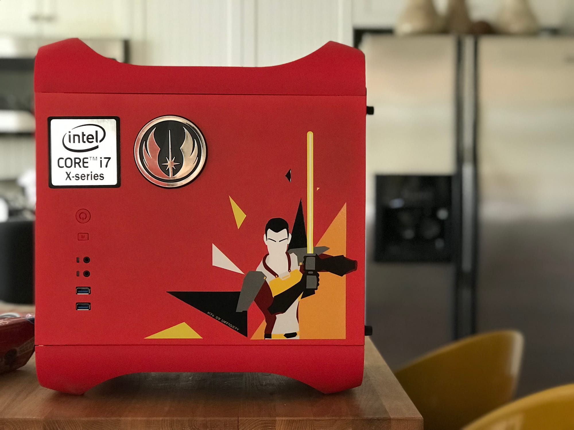
I'm pleased with the sale–it went to a dad gifting it to his son who was turning 13 and just starting their journey into Linux. Knowing that it will be used to train the next generation of IT Jedi (as my former boss once mused on my LinkedIn) puts me at ease with it.
The idea was to migrate over to a supported Apple Silicon device, e.g. M4 Mac mini, but as of right now I'm holding out for either a good price reduction or an M5 variant, whichever comes first. That being said, I decided to limp along on my MacPro4,1 (flashed to 5,1) until that happens.
My biggest issue with this unit was the GT 120 GPU it came with–while it is an Apple EFI card with boot screen and native support, it doesn't support DisplayPort 1.2 (required by my Dell S2716DG) and isn't well-supported in later macOS versions. To rectify this, I decided on the RX 560–cheap, supported in later macOS versions, supports DP 1.2, and with EnableGOP, provides a boot screen–everything I needed to cut out the GT 120.
There are two principle ways to use EnableGOP:
- Inject into Mac system firmware
- Inject into vBIOS
It being GPU-related, and not wanting to muck around with the system firmware more than I already had with the 5,1 conversion, it seemed only natural to lean towards the latter. With this GPU, however, there was just one small problem:
In the case of AMD, considerably less space is normally available, due to a strict limit of 128k for legacy and EFI parts of the larger ROM image. If there is not enough space (i.e. script reports data would be truncated) then it is necessary to strip some legacy VGA parts of the GPU firmware.

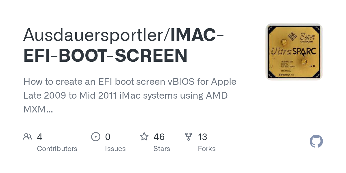
I quickly discovered via running their vBiosInsert.sh that my MSI RX 560 4GB was one of the cards affected by this limit, so it was on me to strip out the VGA part of the vBIOS. Thankfully, someone wrote a very detailed breakdown on how to do this:

Their guide was so detailed that I found it frankly unfriendly to a layman who wouldn't ever have their Calculator.app set to Programmer mode. It was also missing a step that was needed for my card, so I decided to document my process here, hopefully in a more friendly way.
Conceptually, it's quite simple:
- Extract vBIOS
- Enable/update GOP
- Delete VGA portion
- Calculate/correct absolute addresses
- Recalculate checksum
- Flash VBIOS
Extracting the vBIOS with amdvbflash
As per the above OpenCore doc, this can be done in either Windows or Linux using amdvbflash–for the latter, the commands would be:
# Find <GPU number>
sudo /path/to/amdvbflash -i

# Save vBIOS to <file>
sudo /path/to/amdvbflash -s <GPU number> <file>
Enabling/updating the GOP with GOPupd
After I successfully followed and validated my work from the above guide by @Ausdauersportler, I still got a black screen without doing this step, which needs to be done before anything else for the tool to work.
As hinted at here:
[...] Your card must include GOP in its own firmware in order to work with EnableGop. [...] GopUpdater from WinRAID is one good solution for adding GOP to AMD cards. Once you have added GOP to the card and got it working in OpenCore without OCLP Enable AMD GOP, then it should work pre-OpenCore with EnableGop.
On Windows, the tool is extremely simple to use:
To work with GOPupd, you just drop the VBIOS file on GOPupd.bat and follow the instructions.
The resulting file can then be used to proceed with @Ausdauersportler's guide.
"Deleting the VGA"
Initial setup
This step and subsequent ones are primarily in macOS with Hex Fiend, ATOMTableResize, and atomtool.py, but also have a Linux component with AtomDis.
To acquire each, @Ausdauersportler compiled a "Tools and Resources" page:

While their guide is phenomenally detailed, what confused me the most about it is the two screenshots showing what was essentially "draw the rest of the owl". Their finished vBIOS screenshot showed a much smaller ROM Header 1 (which I later deduced to be the EnableGOP driver) and a ROM Header 2 that wasn't present in the original vBIOS (which I later deduced was the old ROM Header 1). This created confusion for me on whether other parts of the vBIOS outside of the legacy portion needed to be touched as well. Coming out on the other side, I can now say explicitly that this mod only encompasses the legacy portion.
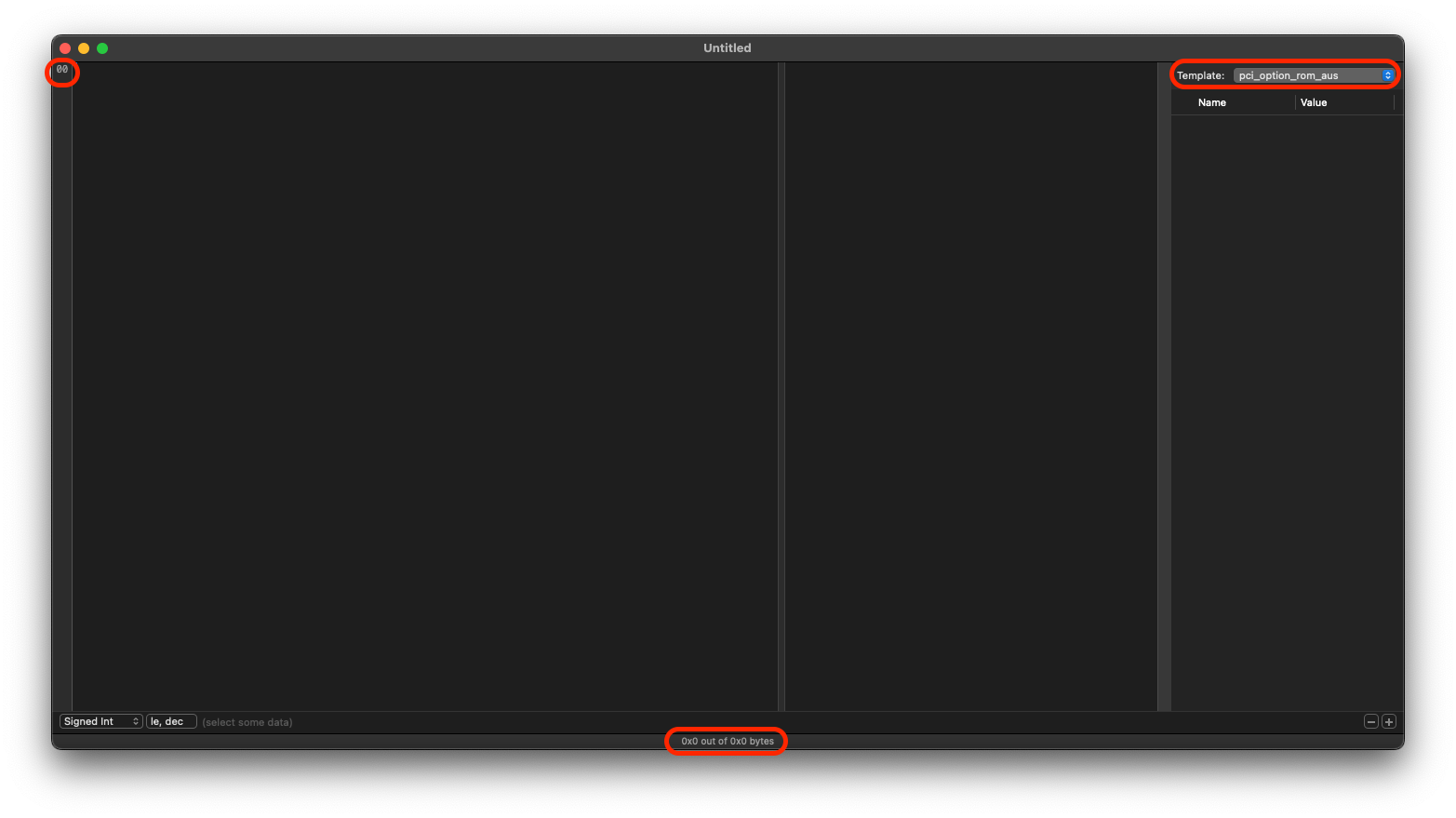
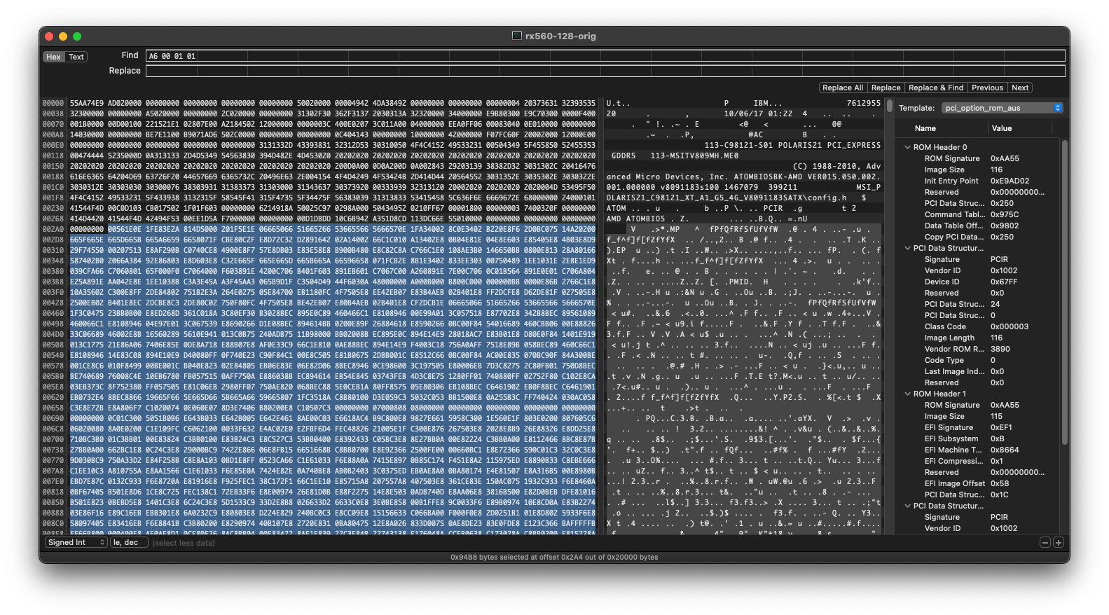
Before doing anything in Hex Fiend, be sure to set up the included Binary Template:
As of Hex Fiend 2.18.1, this can be done by:
- Views > Binary Templates
- Template: > Open Templates Folder
- Place extracted template in folder
- Template: > Select "pci_option_rom_aus" template
Also recommend setting the following in Hex Fiend, which will be important for other downstream steps:
- Hexadecimal line numbers - Views > Line Number Format > Hexadecimal
- Hexadecimal byte indicator - simply click the text at the bottom to switch it to hexadecimal
Hex Fiend should look like this after the above:
Once the vBIOS file from the GOPupd step is open in Hex Fiend with this Binary Template and these settings, we can begin our mods.
Isolating the first 128KB
@Ausdauersportler describes the first step:
[...] Basically all changes to an AMD vBIOS have to made within the first 128k without moving the latter part (if there is one).
To make this more easy one can copy this first 128K from each vBIOS into a separate file and work on this contents, only. After finishing and checking success using the tools described below you can copy back the complete modified block. This way no move of this so called training data beyond the 128k limit can happen (a lot of vBIOS versions are of size 128K and do not need such special treatment).
To do this, simply Command + L and "Move selection to" 0x20000 (which is 131,072 bytes (128KB * 1024) in hexadecimal), then highlight all the way to the beginning of the file. Copy this selection into a new Hex Fiend window and save it out.
Stripping the VGA component
In our newly isolated 128KB file, we can now move to finding/removing the VGA component. Before moving any further–if the Binary Template doesn't show anything after opening the file, simply select it again and it should load.
Noting ROM Header 0 Image Size/Length
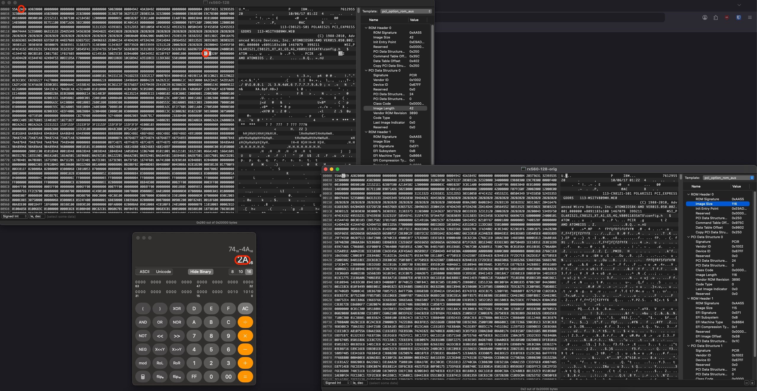
After we cut out the VGA portion, because everything will have moved around, the Binary Template will break until we correct the Image Size and Image Length, so it's important to note down where these values are controlled so we can change them later and re-enable the Binary Template:
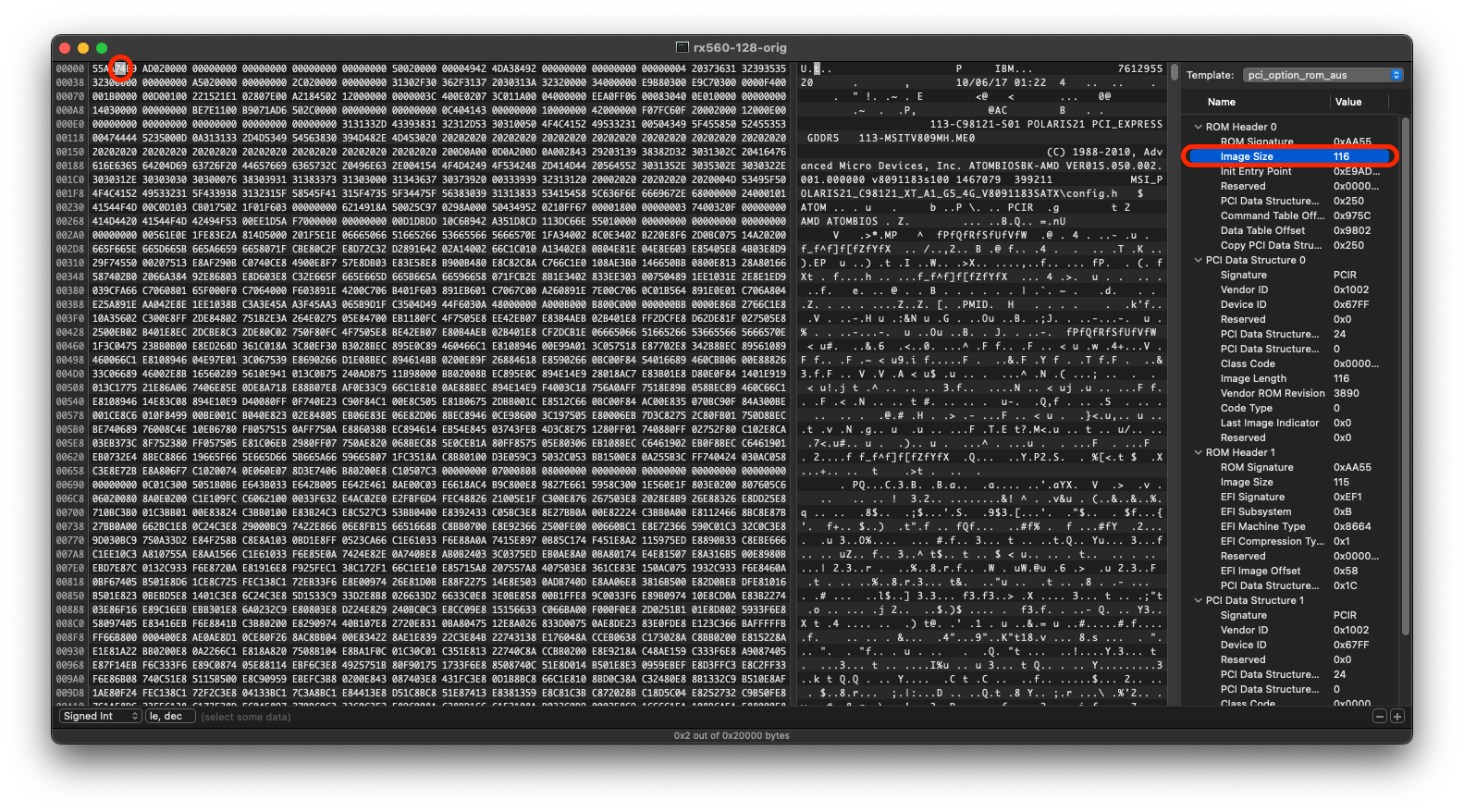
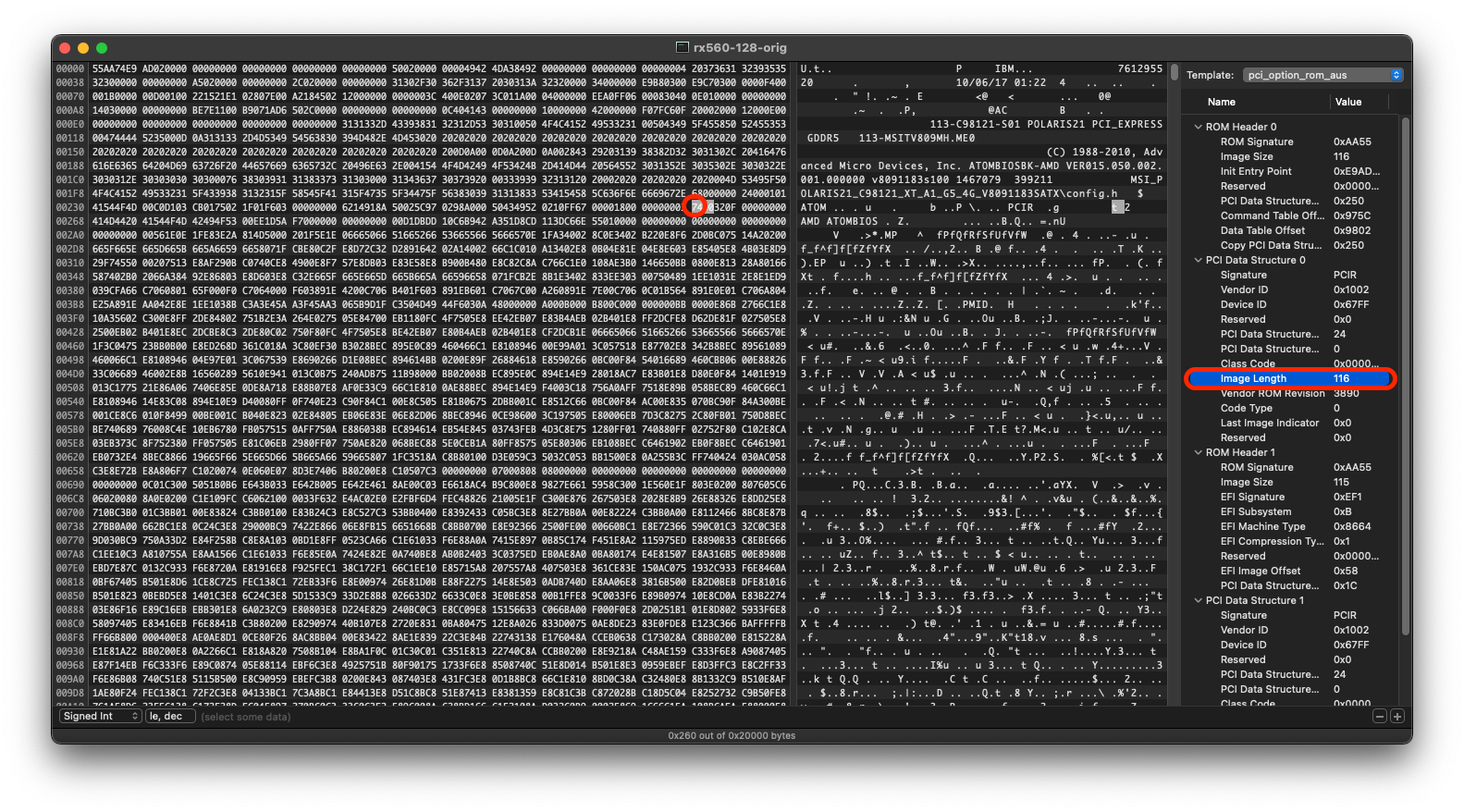
Simply click each value in the Binary Template to jump to it, noting what each one looks like and where it is/will be.
Determining the full selection
Command + F for 00561E0E–it will be evident because there should only be one match and it should correspond to "V" in the plain text view.
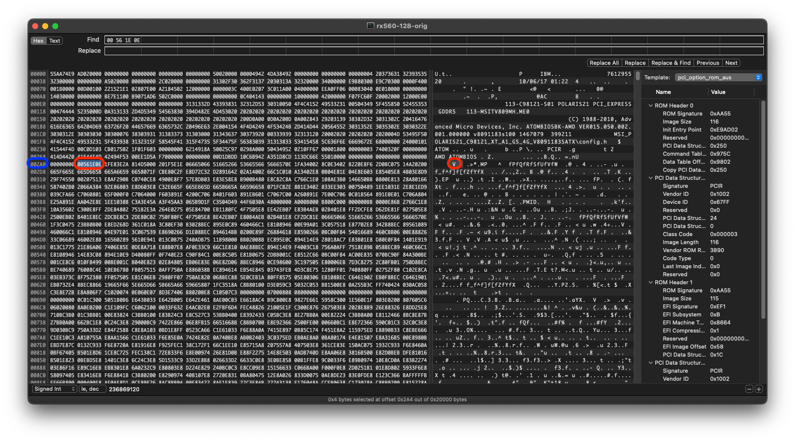
This marks the beginning of the VGA portion and thus our selection. Note down the line number to refer back to later.
@Ausdauersportler tells us the end of our selection:
Luckily this VGA part is stored in a single big binary blob right after the PCIR header of the legacy part and in front of the ATOM data and command tables.
It isn't made textually explicit in their guide but A6000101 is what we need to Command + F for next:
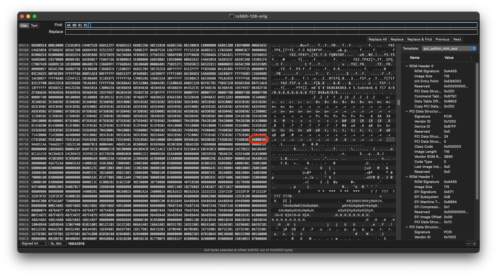
We need to highlight everything starting at 00561E0E from earlier to right before A6000101. We don't include the latter in the selection because it's beginning of the aforementioned ATOM data and command tables. These two values in particular are not unique to my GPU, but rather seem to be universal in AMD vBIOSes.
We can't just hit Backspace quite yet though–we have to account for what @Ausdauersportler lays out:
Some thoughts before starting the cutting process. All vBIOS parts are 512 byte aligned (0x200). [...] So cutting a multiple of 512 bytes would keep the alignment in place, would make it simple to change this image size by just subtracting the number of blocks deleted, and finally would also make the address math much more easy.
So we need to make sure our actual deletion is a multiple of 512 bytes.
Aligning to 512 byte multiples
Notice at the bottom of my window that my selection is 0x94B8 bytes, which as it turns out is not a multiple of 512 bytes. AI to the rescue:
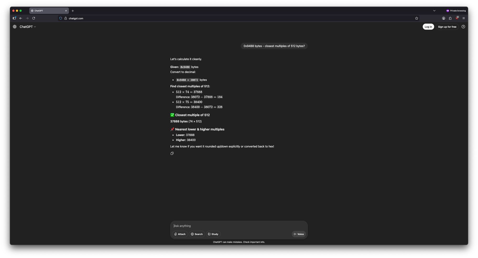
In my case, the "512 x 75 = 38400" option would exceed the 38072 (the earlier 0x94B8 hexadecimal number converted to decimal) byte size of my original selection, so in my case there is no other path forward besides the "512 x 74 = 37888" option. Note down the bytes and the multiple in both decimal and hexadecimal for use later.
| [My] Value | Decimal | Hexadecimal |
|---|---|---|
| Bytes | 37888 | 0x9400 |
| Multiple | 74 | 0x4A |
Values will vary per GPU so don't simply use mine.
A quick and easy trick to get the hexadecimal value is to type the decimal value in Calculator.app's Basic mode, then simply switch to Programmer mode. For example, for the "Bytes" value above:
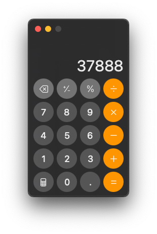
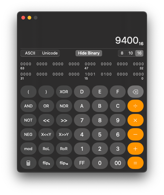
0x to the front of this value when referencing back to itSelecting/deleting our 512 byte multiple
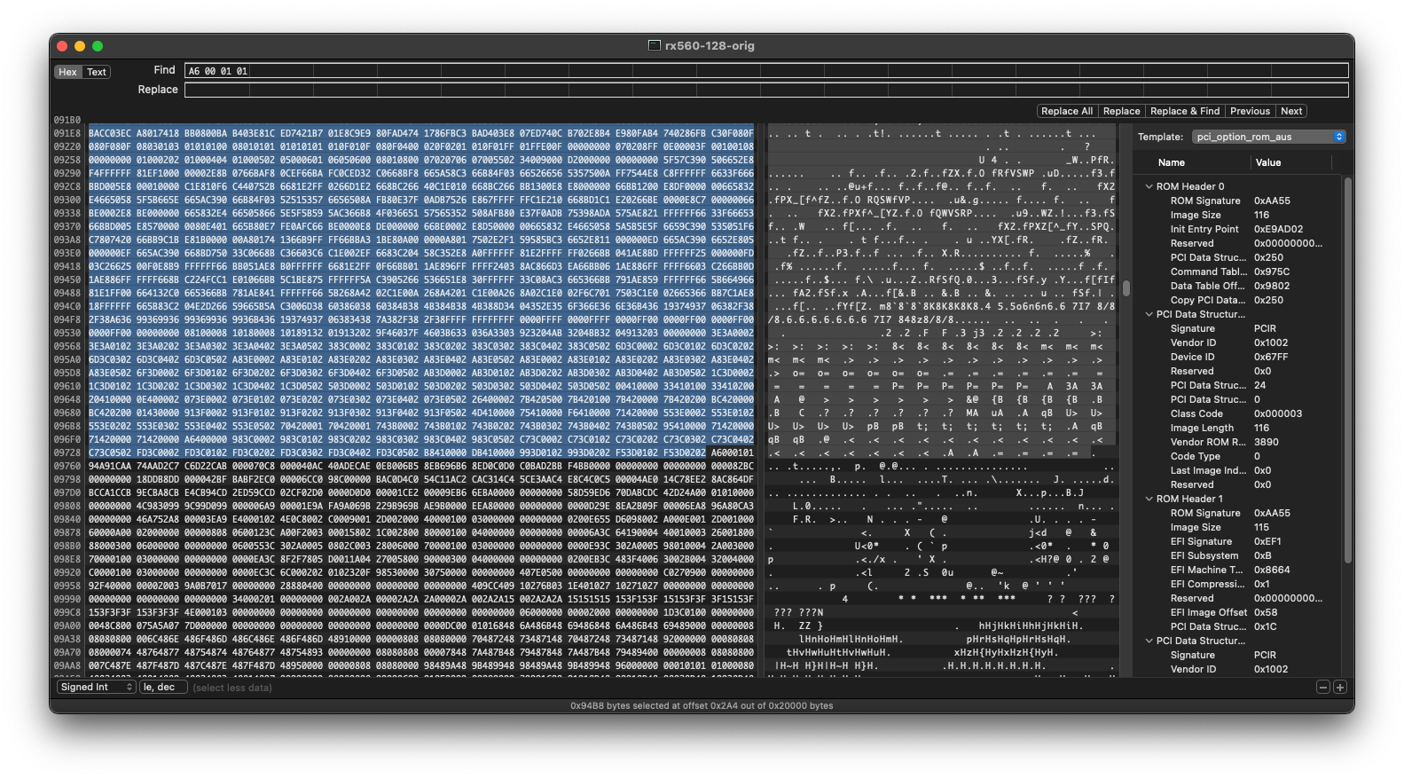
To get our new end selection, highlight from our previous 00561E0E starting point ("Beginning of VGA selection" screenshot above) until Hex Fiend reports that we've selected the new byte amount we calculated:
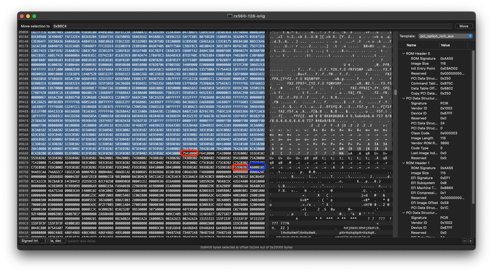
In my case, notice at the bottom that the "bytes selected" matches what I calculated earlier for "Bytes" in hexadecimal. In blue, notice our old A6000101 end point, and the disparity of data in between our old and new selections–had we simply Backspace'd before, we would have lost the structure outlined by @Ausdauersportler. The beginning and end of this disparity is highlighted in red because we'll need to note this down for later.
We can now Backspace our selection, which should delete a significant amount of data. To not lose our place, recommend scrolling to the top of the selection before hitting Backspace.
Sanitizing the VGA component remnants
According to @Ausdauersportler:
Additionally the remaining fragments of the VGA part can be happily ignored but you can manually overwrite these bytes with 0x00 - I did this to have a more clean view on the result.
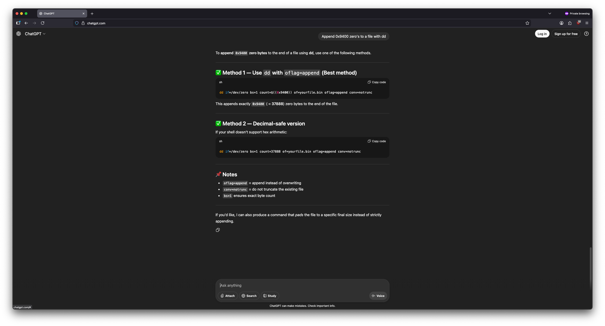
To be uniform with this, we can leverage dd to write 0's to the disparity left behind. Start by highlighting the disparity with the start/end we noted earlier:
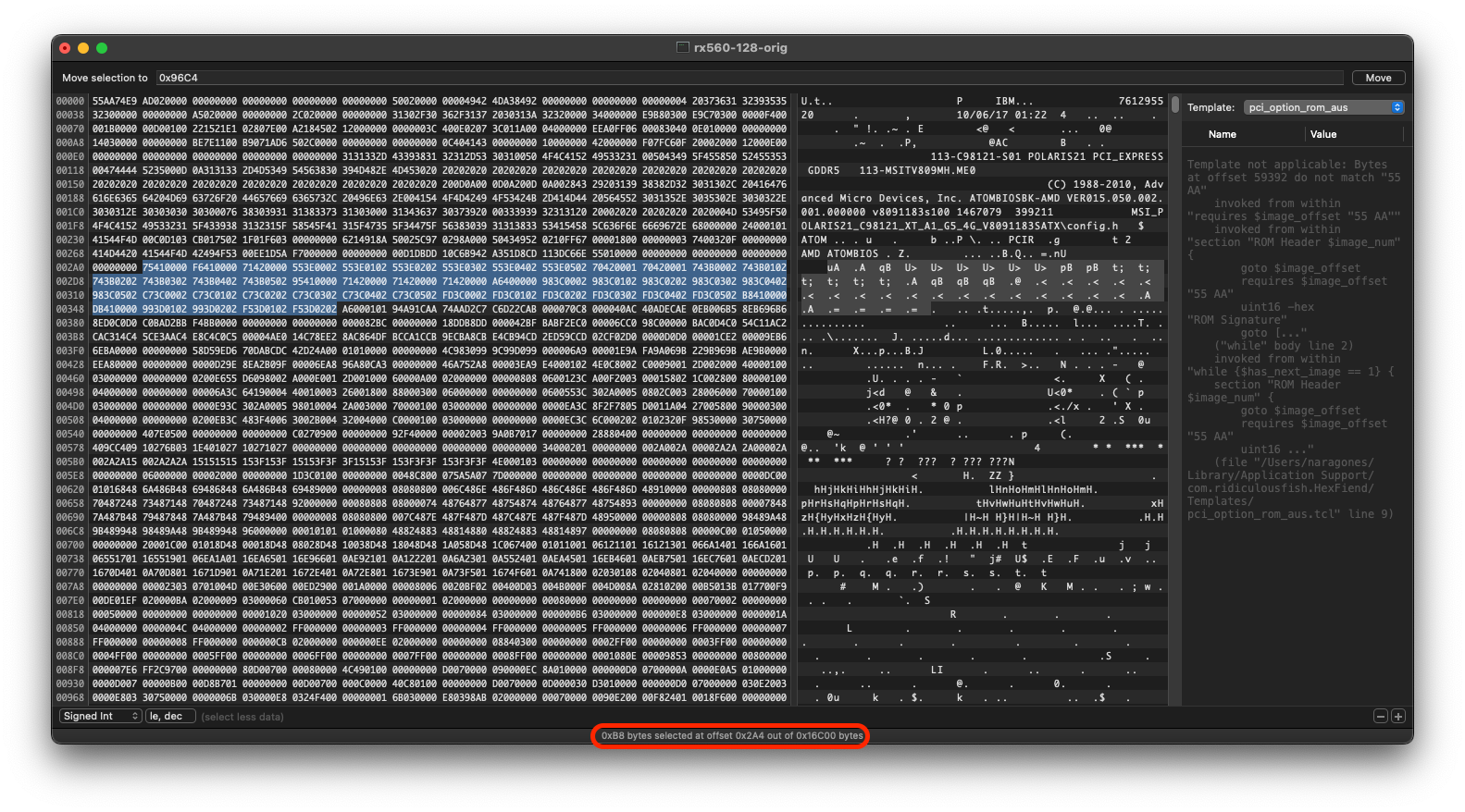
The important piece is at the bottom–we need a dd command to write 0's here:
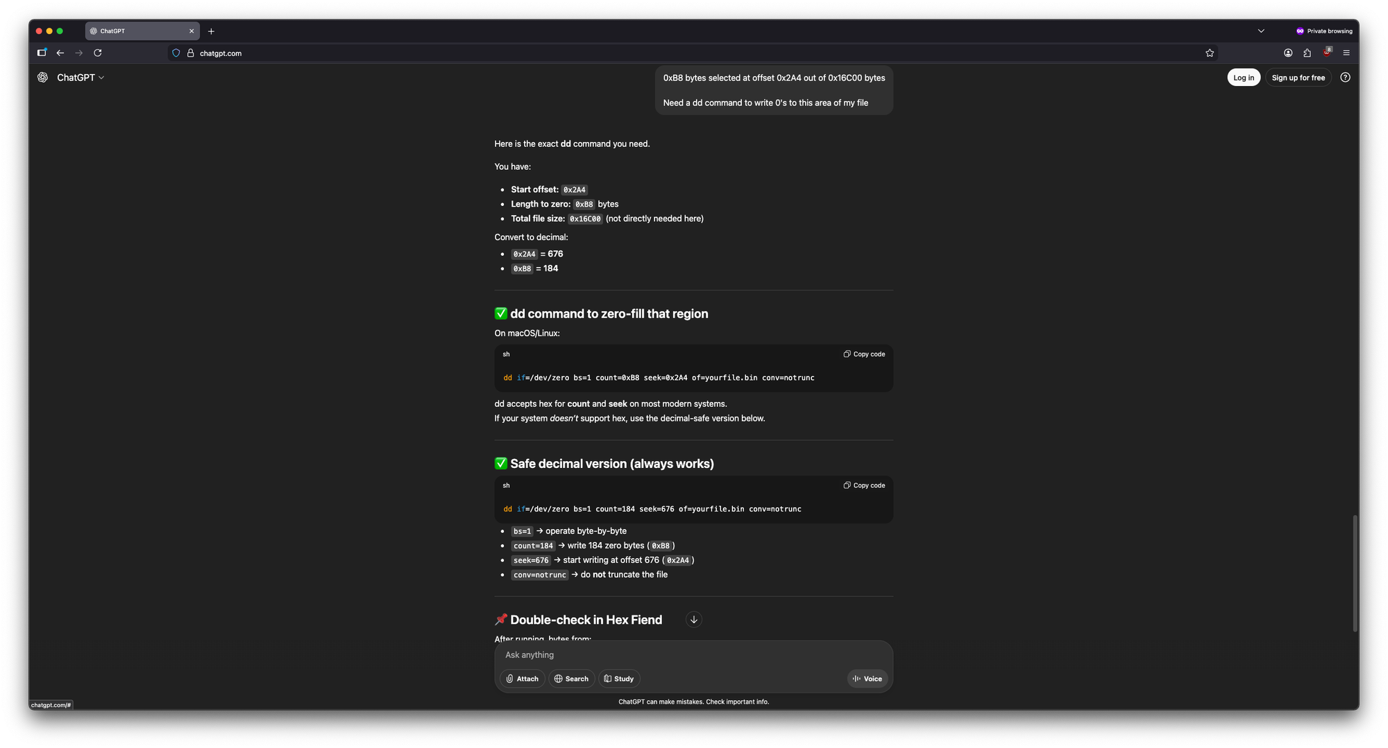
Reopening the file after running this command should show 0's where the disparity used to be.
Adding padding
Per @Ausdauersportler:
To maintain the structure of data potentially stored in larger vBIOS chips beyond the 128k limit we would have to fill the first 128K bytes with padding information (0x00 bytes) of he same length as we just cut from the VGA part.Once again, dd can do this for us. Refer back to your notes for the hexadecimal amount of bytes Backspace'd–in my case, it was 0x9400:
After this step, the file should weigh in at 128KB again.
A brief interruption to note that all of these changes should be enacted on our isolated 128KB file and not the full vBIOS file.
Fixing the absolute addresses
Fixing the Binary Template and Table Offsets
To further progress, we need to fix the Binary Template, which would still be broken at this point. Refer back the info captured in section "Noting ROM Header 0 Image Size/Length" (namely the values and locations), as well as the hexadecimal value of "Multiple" from section "Aligning to 512 byte multiples" (don't use my exact value). We will need to subtract the latter from the former using Programmer mode in Calculator.app–in my case the equation would be 74 - 4A:
The Binary Template should be functional again.
Next, we need to fix "Command Table Offset" and "Data Table Offset" in ROM Header 0. Refer back to the hexadecimal value for "Bytes" in section "Aligning to 512 byte multiples" (use your own value)–we would subtract that from each of the aforementioned Offsets. Consider the above screenshot–for my "Command Table Offset", 0x975C - 0x9400 = 0x35C:
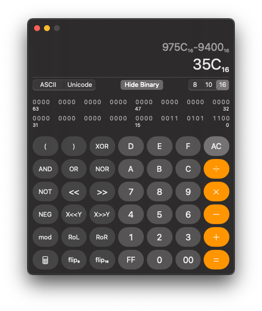
When jumping to each Offset via the Binary Template, notice that the values are byte flipped (e.g. 0x975C is 5C 97 in the file)–we need to do the same thing with our new values. If the byte flip is done correctly, the correct value should show in the Binary Template; for example, my new Command Table offset 0x35C would be edited in as 5C 03 , which should display "0x35C" in the Binary Template.
Fixing Table Absolute Addresses
All that's left is fixing the absolute addresses in the Command and Data Tables themselves. It is at this point that we will need atomdis, which I used Linux for.
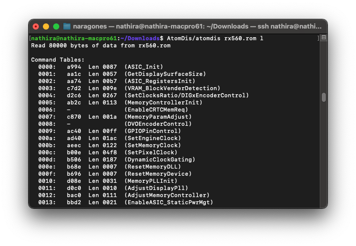
@Ausdauersportler's instructions here are very robust:
You can easily detect the pattern, only the 2nd byte of each address has been changed
The screenshots in their guide are easily adaptable to a wide array of VBIOSes. What isn't immediately obvious is the "important note" at the bottom of the guide:
atomdis does not show all data tables. [...] If ATOMTableResize refuses to load the modified vBIOS file you likely missed this hidden table.
In my case, I had two hidden tables - one hidden Command Table, and one hidden Data Table. As an example, the change to the former looked like this:
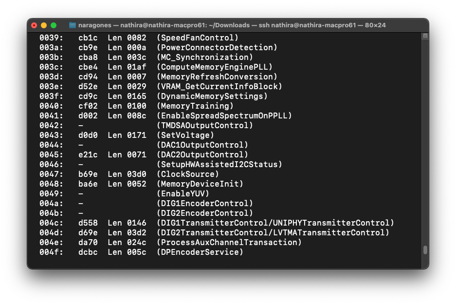
dcbc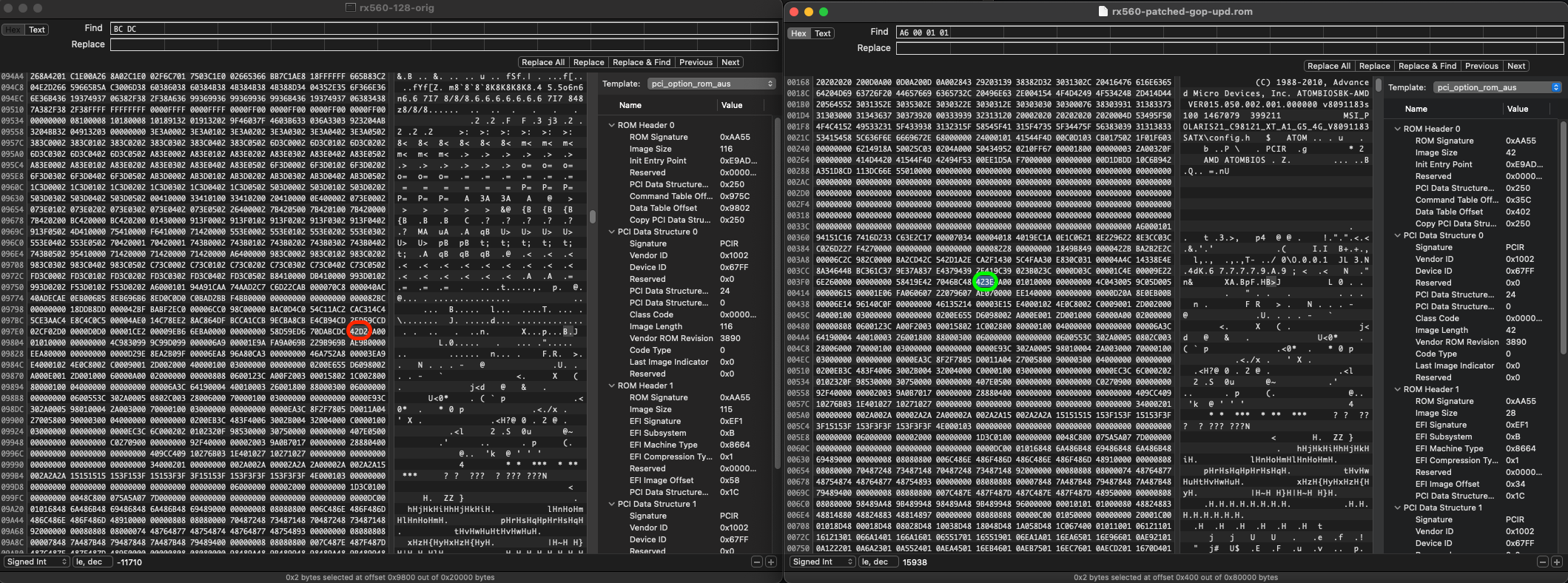
As @Ausdauersportler mentioned, a success case will be obvious if ATOMTableResize opens the file.
Fixing checksum
@Ausdauersportler tells us:
Final step, most important one:
Since we changed the legacy part the checksum will be wrong.
I didn't have a lot of success with ATOMTableResize's "Fix and save everything" function - it didn't really do anything. However, atomtool.py is listed in Tools and Resources as "fixes checksum and allows table changes", and this is what ended up giving me the correct checksum.
Conclusion
After a reflash to the GPU with amdvbflash, there should be a functioning boot screen!